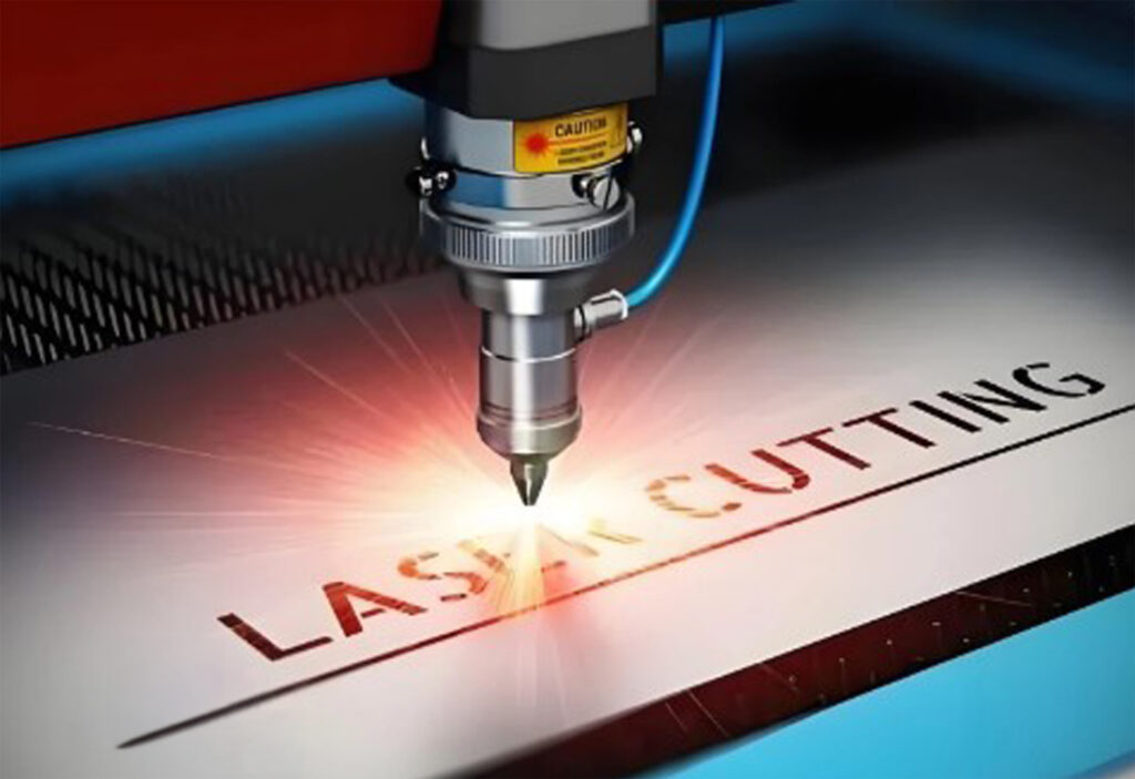
Made with excellent technology and materials, it enables precise and accurate cutting
JLCut Solution
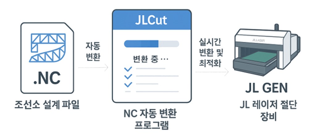
NC Automatic Conversion Solution, JLCut
Connect design data to laser cutting with just one click.
Connect design data to laser cutting with just one click.
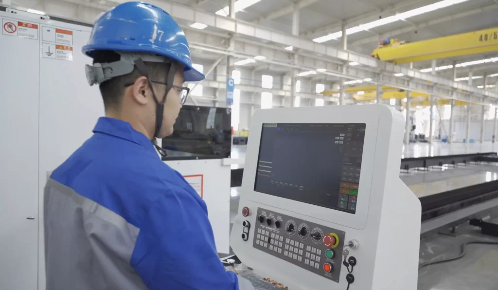
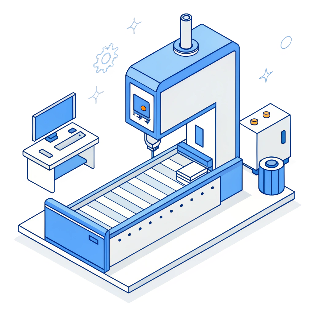
JLCut, used in industrial sites like this.
JLCut used in industrial sites like this.
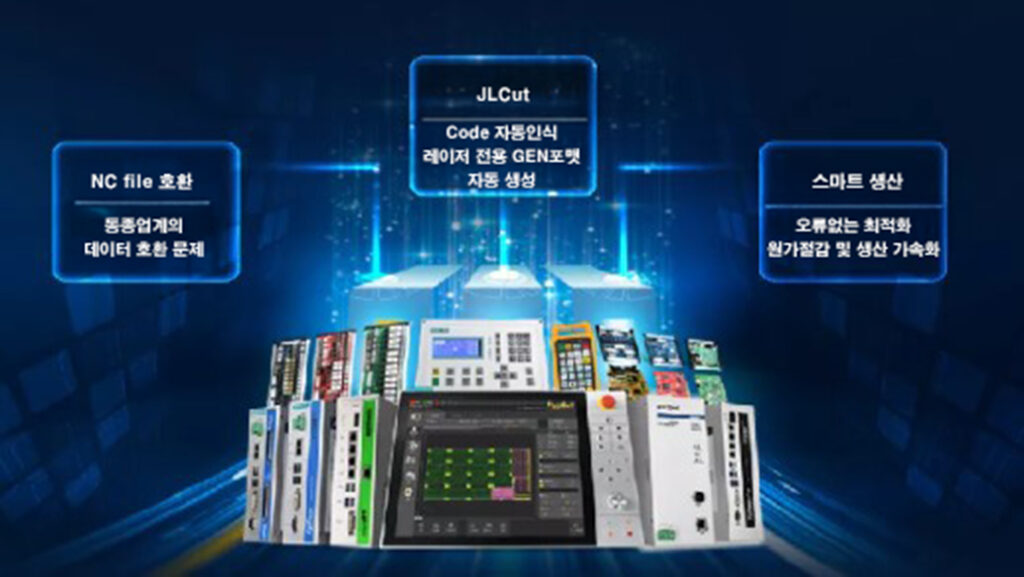
Why is NC conversion necessary?
NC files are configured for plasma/gas cutting equipment.
Laser equipment requires GEN format.
Manual conversion leads to quality degradation and time waste.
Frequent human errors due to repetitive tasks.
JLCut, connects automatically
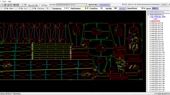
Automatically recognizes and analyzes various NC formats
Automatically generates laser-specific GEN format
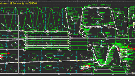
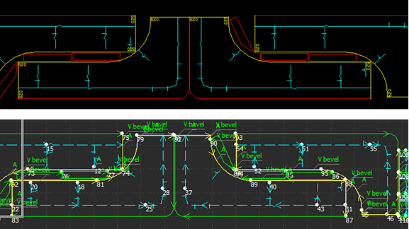
Automatically removes corner loops and inputs bevels
Deletes entry/exit lines and removes duplicate paths
User-friendly interface, easy to use by anyone
The Amazing Application Effects of JLCut
Improved drawing processing capacity: 100 cases per day → 5000 cases
Reduced quality defect rate: 0.3% → 0.0%
Enhanced workforce efficiency, reduced burden on skilled workers
Error-free optimized cutting paths
Digital transformation begins here.
Solves NC data compatibility issues between shipyards and partners
Increases productivity and reduces costs
Accelerates the transition to a smart production system
Quote request
JL Tekla Component
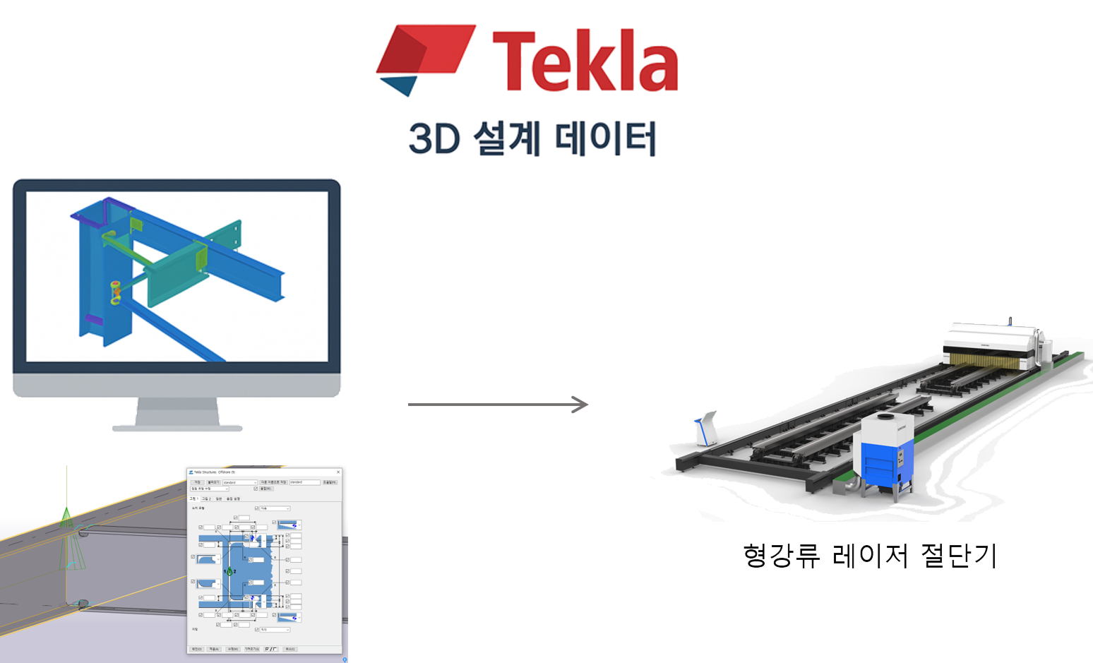
“Send Tekla-based 3D design data directly to JL’s cutting machine.” The BIM-based cutting solution that connects design to processing, revolutionizing productivity begins now.
“Send Tekla-based 3D design data directly to JL’s cutting machine.”
The BIM-based cutting solution that connects design to processing, revolutionizing productivity begins now.
Why Tekla?
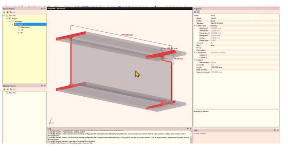
Tekla Structures is a 3D modeling-based steel structure design program that allows for the accurate modeling of structural components (such as beams, columns, plates, etc.) with precise shapes and dimensions.
Tekla Structures is a 3D modeling-based steel structure design program that allows for the accurate modeling of structural components (such as beams, columns, plates, etc.) with precise shapes and dimensions.
Complex profiles and structures can be represented in detail. NC data is automatically generated to improve processing efficiency. BOM (Bill of Materials) automation simplifies fabrication and ordering. Collision checks and interference prevention to avoid errors.
Complex profiles and structures can be represented in detail. NC data is automatically generated to improve processing efficiency. BOM (Bill of Materials) automation simplifies fabrication and ordering. Collision checks and interference prevention to avoid errors.
Connecting design and manufacturing
Convert the structural data designed in Tekla into NC files and transfer it to the JL cutter.
Convert the structural data designed in Tekla into NC files and transfer it to the JL cutter.
Precision cutting without error
Based on BIM design data, high-precision cutting with an accuracy of ±0.2mm is possible.
30% reduction in work time
No need for drawing interpretation or manual input, significantly improving process speed.
No need for drawing interpretation or manual input, significantly improving process speed.
Tekla + JL Laser Cutter = The Best Productivity
Tekla + JL Laser Cutter
The Best Productivity
By linking the NC data generated based on the structural model designed in Tekla directly to the laser cutter, the following advantages are achieved
By linking the NC data generated based on the structural model designed in Tekla directly to the laser cutter, the following advantages are achieved
Items
Traditional Cutting Method
JL Laser + Tekla Component
Drawing Interpretation Time
Manual interpretation required
Automatic NC data extraction
Error Rate
Possible errors due to manual input
Consistent design and production data
Production Speed
Individual work for each drawing
Model-based mass cutting available
Precision
Plasma/processing errors exist
Laser precision cutting (within ±0.2mm)
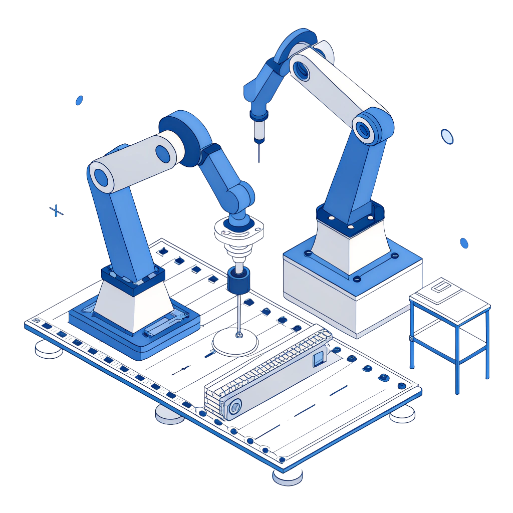
Tekla, used in the industry in the following ways
Applications
Cutting of structural steel for shipbuilding and marine structures
Can be integrated with production process monitoring programs
Automatic reflection of design changes (Optional)
Quote request
3D Profiling
It can cut any shape.
Profile
Applicable Industries: Construction / Marine / Shipbuilding / Others
3D Profiling
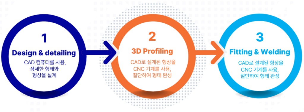
The 3 Step Precess
CAD profiling is a manufacturing process that cuts three-dimensional shapes into metal pipes, beams, and other steel profiles. This process begins by creating a 3D model of the desired steel parts using computer-aided design (CAD) software like Tekla. The model is then transferred to a specialized cutting machine, which uses high-output plasma or oxy-fuel torches to precisely cut the steel into the desired shape.
CAD profiling is a manufacturing process that cuts three-dimensional shapes into metal pipes, beams, and other steel profiles.
This process begins by creating a 3D model of the desired steel parts using computer-aided design (CAD) software like Tekla.
The model is then transferred to a specialized cutting machine, which uses high-output plasma or oxy-fuel torches to precisely cut the steel into the desired shape.
1. Design and Detailing
3D profiling is performed through the connection of CAD-CAM (Computer-Aided Design and Computer-Aided Manufacturing) and CNC cutting machines.
The cutting dimensions may also include additional welding specifications such as shrinkage, groove angles, and root openings.
2. 3D Profiling of Steel
Depending on the specifications, plasma or oxy-fuel cutting torches are selected and mounted on the robotic arm of a CNC cutting machine.
This profiling process compensates for material distortions such as curved beams or deformed pipes.
The compensation is achieved through a combination of laser measurement systems and sophisticated mechanical engineering.
3. Assembly and Welding
Thanks to the welding preparations applied during the design and detailed design phase, optimized assembly and welding can be carried out immediately after profiling.
Parts align easily, and the welding volume is significantly reduced, leading to substantial savings in both time and cost.
Applications
Cutting of structural steel profiles for shipbuilding and marine structures